Technical challenges of flying close to the Sun
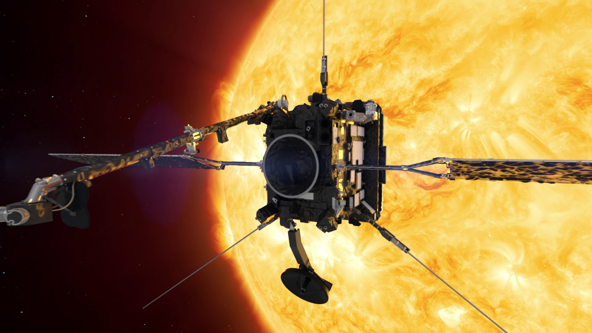
Solar Orbiter was many years in the making: the first mission study took place in ESA’s Concurrent Design Facility back in 1999. The concept was to create a spacecraft that would venture as close to the Sun as possible and still image it, without its cameras melting. From the start the concept was that Solar Orbiter’s instruments would peep through a multi-layer heatshield, to protect the main body of the spacecraft from the searing sunlight of the Sun – at 42 million km away some 13 times as intense as that experienced in Earth orbit.
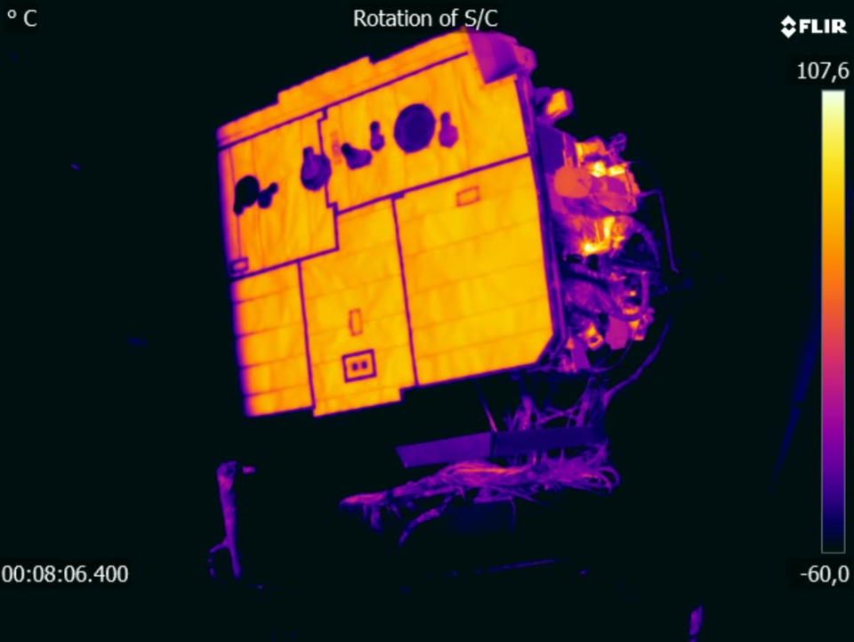
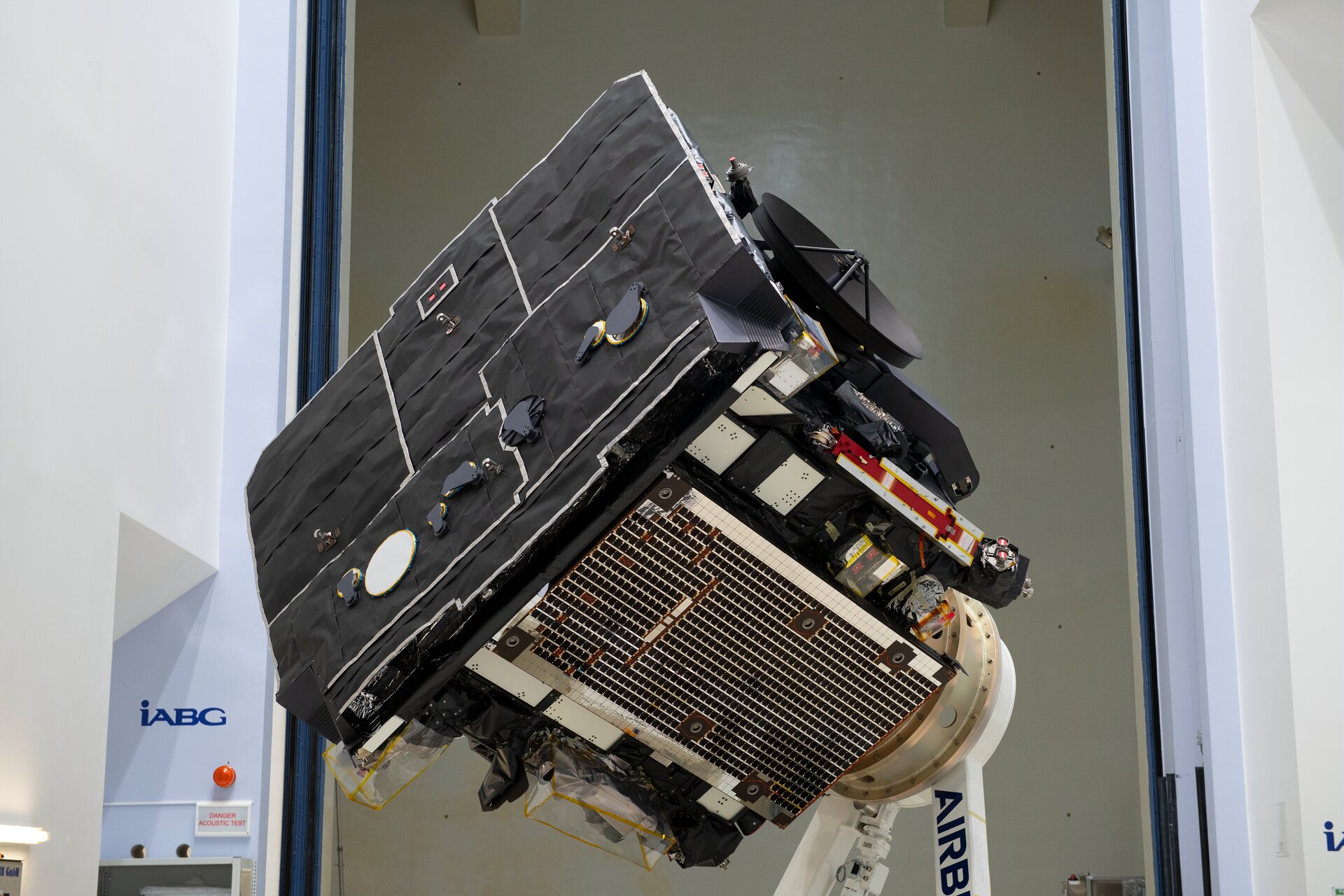
The mission’s 3.1 m by 2.4 m heat shield starts with a thin surface layer of titanium foil just 0.05 mm thick – around the width of a human hair – that is backed up by 18 layers of specially tailored titanium multilayer insulation.
This layering is linked by titanium brackets across a 24.5 cm gap to an aluminium honeycomb support panel covered with high thermal conductivity carbon fibre skins and insulated by another 28 multi-layer insulation layers. This support panel is linked to the main spacecraft body across another 10 cm gap.
Designing and building this intricate structure was difficult enough, but the greatest engineering challenge was embodied in its topmost, Sun-facing layer.
The search for a sunscreen

“The mission had three main requirements for the heatshield covering,” explains ESA materials engineer Andrew Norman.
“Firstly it had to keep the same colour during years of exposure to intense solar flux, including high ultraviolet radiation – the mission team would have loved a white coating, to reflect back more solar energy, but testing showed it would darken unacceptably over time. So we settled on black, to keep its thermo-optical properties stable over the mission lifetime.
“Secondly it had to be electrically conductive, to prevent any build-up of static from interaction with the solar wind, which might do damage to the spacecraft by discharging and disturb the payload’sprecise measurements of electrons in the solar wind. Finally there could be no outgassing or shedding of particles, which might endanger the mission’s instrument lenses, mirrors and sensitive surfaces.”
This combination of requirements proved too much. Existing paints or coatings either could not withstand the solar heat and radiation or were not conductive across the required temperature range. And in vibration testing they released too many particles.
“We were left to consider the option of bare, uncoated titanium,” notes ESA thermal engineer Claudio Damasio. “But this would have led to temperatures of 700 °C onthe Sun-facing side of the heat shield, and required a much bulkier shield structure with extra multilayer insulation. We needed a different solution, and thanks to Irish company Enbio we found it.”
Caveman’s solution

Enbio’s technique, called ‘Co-Blast’, originally developed for medical implants, involves grit-blasting away a metal’s surface oxide layer to chemically bond a new coating onto it. The coating effectively becomes part of the metal, so it never comes off.
The company tested different coatings, notes Enbio’s Managing Director John O’Donoghue: “I recalled cavemen used burnt bone for cave painting, along with charcoal – and its durability is proved by the fact the paintings survive to this day. We found a US company called Ebonex who produce a char bone pigment – they burn the bone in low oxygen, then crush it, so all the fat and tissue is gone. It turned out the pigment already had space heritage, having been employed by NASA.”
“For us, this effectively saved the project,” adds Claudio. “It meant the surface would retain constant ‘thermo-optical properties’ – maintain the same black colour despite years of exposure to extreme ultraviolet radiation – so we keep thermal stability throughout the mission, setting maximum surface temperature at 520 °C and no more.”
Known as ‘Solar Black’, this black coating ended up applied to other Sun-exposed parts of Solar Orbiter, so the spacecraft evolved from a largely white object with a few black surfaces to a largely black object with a few white surfaces.
Peeping through the shield


Access the video
The intricate heatshield with its coating wouldn’t be enough to protect Solar Orbiter’s sensitive instruments and allow them to make accurate measurements.
The mission carries two types of instruments. The so-called in situ instruments measure properties of the environment in the vicinity of Solar Orbiter and are mounted on a 4.4 m boom at the back of the spacecraft. Then there are the remote-sensing instruments, various types of imagers and telescopes that photograph the Sun at different wavelengths.
Most of the remote-sensing instruments need to look at the Sun directly. To enable that, the engineers cut tiny windows into the heatshield, which open only at times convenient for the observations. Since the temperature behind the shield is still too high for some of the sensitive electronics to work, each instrument requires its own thermal optimisation design.
“The front of the SPICE instrument behind the heatshield is about 120 °C,” says Martin Caldwell, the Project Manager of the Spectral Investigation of the Coronal Environment instrument SPICE, which was built byan international consortium led bythe UK laboratory RAL Space. “But our detector requires a temperature of −20 °C to make accurate measurements.”
SPICE studies the temperature and thecomposition of the Sun’s hot atmosphere, the corona, which gives rise to the solar wind. To do that, it takes spectral images of the Sun in the extreme ultraviolet part of the solar spectrum. Similar instruments have been flown on Sun-observing missions in Earth orbit, but those weren’t exposed to such high temperatures and amount of light.
“Most of the light that enters the 80 cm-long instrument is in the visible and infrared part of the spectrum, which is not only of no use to us but also has a heating effect,” says Martin. “We therefore coated the mirror at the back of the instrument with boron carbide, which only reflects the extreme ultraviolet light into our detector compartment, and lets the rest pass through back to space.”
Freezing cold inside

Still, a layer of insulation is needed to protect the detector box from getting too warm. The temperature around the detector compartment is around 50 °C, way too high for accurate measurements. But even the insulation wouldn’t be enough to achieve the required −20 °C.
Two silicon detectors inside the box, each only about 1.5 cm in size, are therefore connected with what engineers call a cold strap to an aluminium radiator on the shielded side of Solar Orbiter. In the vacuum of space, the temperature difference between the illuminated and shaded side of the spacecraft is huge. Even with 500 °C at the front, the back of the spacecraft could be as cold as −200 °C.
The system of radiators, the Stood-off Radiator Assembly, or SORA, is one of the technologies designed specifically for Solar Orbiter.
The cold straps connecting the instruments to the radiators are made of pyrolytic graphite, a highly conductive material consisting of layers of carbon.
“Pyrolytic graphite is five times more conductive than copper and extremely flexible,” says Ian Walters, Solar Orbiter Project Manager at prime contractor Airbus Defence and Space, which built the spacecraft at its UK facilities in Stevenage. “The flexibility is extremely important because everything stretches under the heat load and also everything vibrates when we launch.”
Intelligent solar arrays


Access the video
Solar Orbiter’s solar arrays presented another engineering challenge. The temperature the cells are exposed to varies with the spacecraft’s distance from the Sun. At its closest (42 million km from the Sun) the temperature far exceeds 300 °C, which is the maximum for the cells to work efficiently. At its farthest (153 million km away from the Sun, just a little over the average Sun-Earth distance) the temperature is much lower. Over the mission’s planned 10-year life span, the solar panels will undergo about 20 hot-cold cycles, which will erode them more than if they were constantly hot, as in the case of the Mercury probe BepiColombo. The solar arrays therefore have to be tilted as the distance from the Sun changes to ensure the temperature stays within the required limit.
“When we are very close, at 42 million km, the solar array gets tilted 78° away from the Sun, so that it’s almost edge on,” says Ian. “Otherwise it would get too hot and that would cause a lot of problems, the glues would stop being glues and the solar cells could detach, bend or distort. They would deteriorate rapidly; we would lose power and that would be mission over.”
Solar Orbiteralso runs intelligent software that autonomously controls the solar arrays when the spacecraft doesn’t see its ground control stations. The reliability of the software is critical since Solar Orbiter spends up to three months at a time out of the sigh of the ground stations when on the other side of the Sun than Earth.
“If you get the tilting wrong, even only one degree, it can have mission critical consequences,” adds Ian. “If the solar panels are stuck or not rotating for whatever reason, the software must recover from that extremely quickly and automatically because there is no chance for the ground to intervene.”
The ability of the solar panels to survive in the extreme environment and provide enough power for the spacecraft’s system is one of the key factors that will determine how long the Solar Orbiter mission will last.


